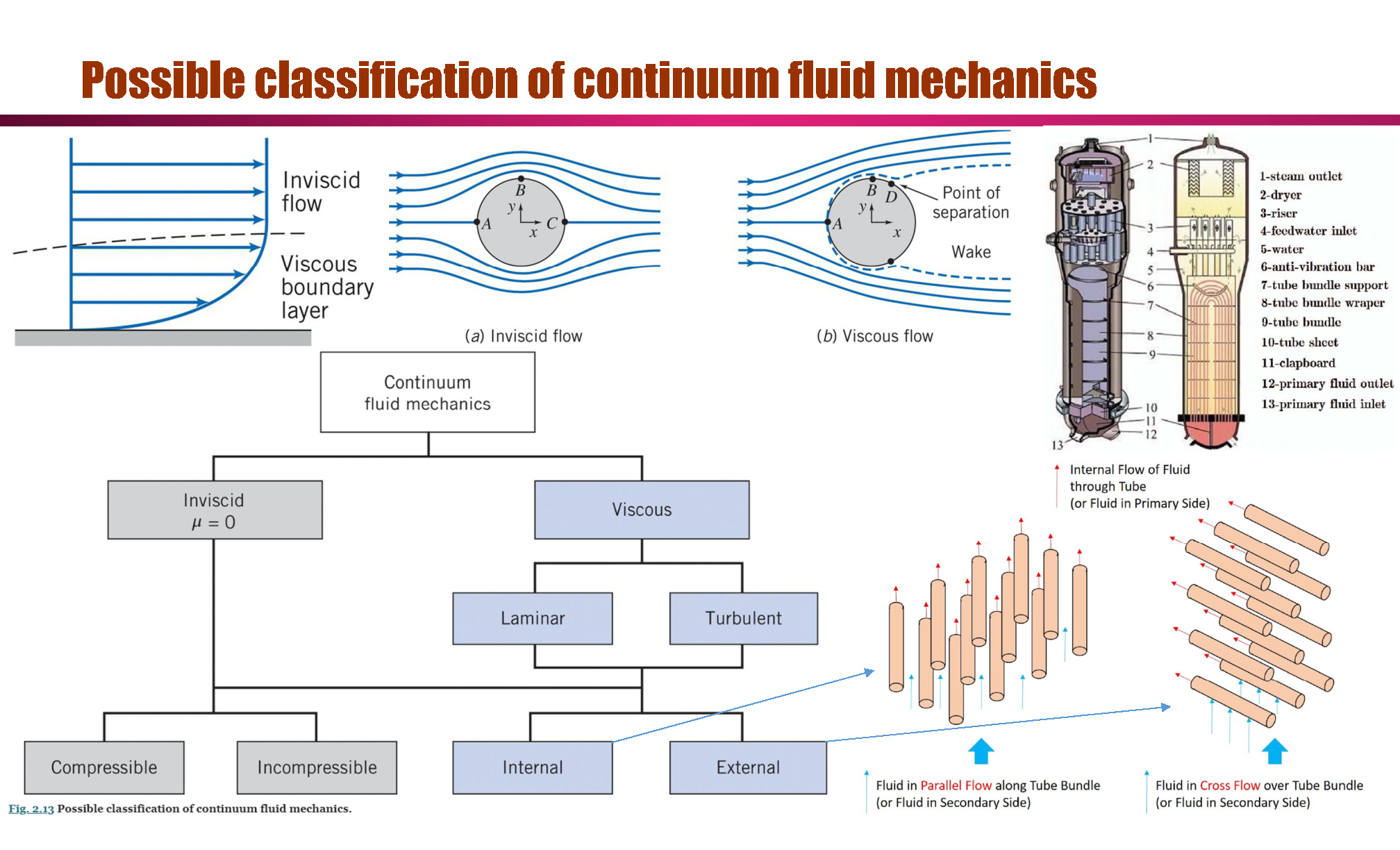
Two Phase Flow: Introduction
Fundamental technical terms
- Flow regime map
- Void fraction
- Interfacial area concentration
- Frictional pressure drop
Review of Single-phase Fluid Mechanics
Basic equations in integral form for a control volume:
Conservation of Mass:
Momentum Equation for Inertial Control Volume (External force = Surface force + Volume force):
For steady flow with no friction, flow along a streamline and incompressible flow (Bernoulli’s equation):
The First and Second Laws of Thermodynamics:
Energy = Heat + Work
Inflow + Local change + External source = Outflow
Derivation of Bernoulli’s equation
- From the continuous equation:
with conditions:
- Steady flow
- No flow across bounding streamlines
- Incompressible flow
- Inviscous flow
- For Momentum equation:
with condition: No friction, so
The 1st and 2nd terms are pressure forces on the end faces of the control surface. The 3rd term is
The body force component in the
But
The momentum flux will be
since there is no mass flux across the bounding stream surfaces. The mass flux factors in parentheses and braces are equal from continuity, so
Substituting Equations into the momentum equation gives
Dividing by
or
Introduction to differential analysis of fluid motion
Conservation of Mass:
Momentum Equation: (Navier-Stokes equations)
For incompressible flow with constant viscosity. (Gravity + Pressure force + Shear stress)
Dimensional analysis and similitude
Conservation Eqs., Momentum Eqs.:
If using dimensionless variables:
Then
Usual dimensionless number for heat transfer:
| Dimensionless Number in heat transfer | Value |
|---|---|
| Biot number | |
| Graetz number | |
| Grashof number | |
| Jakob number | |
| Nusselt number | |
| Prandtl number | |
| Rayleigh number | |
| Stanton number |
Usual dimensionless number for fluid mechanics:
| Dimensionless Number in Fluid Mechanics | Value |
|---|---|
| Reynolds number (inertia to viscous): | |
| Prandtl number (Kimematic viscosity to thermal diffusivity) | |
| Euler number (pressure to inertia): | |
| Drag coefficient | |
| Lift coefficient | |
| Cavitation number: | |
| Froude number (inertia to gravity): | |
| Weber number (inertia to surface tension): | |
| Mach number (inertia to compressibility): | |
| Centrifugal pump specific speed (in terms of head | |
| Centrifugal pump specific speed (in terms of head |
Internal incompressible viscous flow
Flow in the entrance region of a pipe:
Fully Developed Laminar Flow in a Pipe, see Internal Flow for more details
laminar vs. turbulent 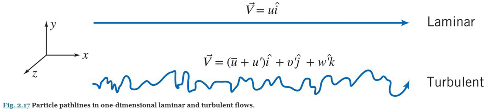
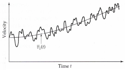
Time-averaged momentum equation for incompressible fluids
Know that
Then for Mass conservation eq.:
For Momentum conservation eq. (
With time averaging:
Know that Stress = Viscous Stress + Turbulent Stress (Reynolds Stress):
let:
Turbulent velocity profiles in fully developed pipe flow
Prandtl proposed a model for the turbulent viscosity based on mixing in the flow. He hypothesized that the turbulent fluctuations in the mean velocity
The quantity
In homogeneous turbulence, the fluctuations
The turbulent shear stress is then approximated as
Further, Prandtl hypothesized that the mixing length
Although this is all very approximate and intended mainly to provide some insight into the mechanisms that transfer momentum in a turbulent flow, it has proved very useful in understanding and modeling turbulent flows.
The total shear stress is the sum of the laminar and turbulent shear stresses. Very near the wall the laminar contribution dominates. Further, very near the wall, the shear stress is essentially equal to the value at the wall. In this wall layer, the shear stress is then given by
It is convenient to introduce the friction velocity,
Further, it is convenient to work with wall coordinates
The relation for shear stress near the wall can then be written as
where
This is readily integrated to yield a linear velocity profile
In the flow farther from the wall, but still near enough the wall that the total shear stress equals the wall value, the laminar stress is much smaller than the turbulent stress. Neglecting the laminar contribution gives the relation
In wall coordinates
where
This relationis integrated to yield
Using experimental data, the constant
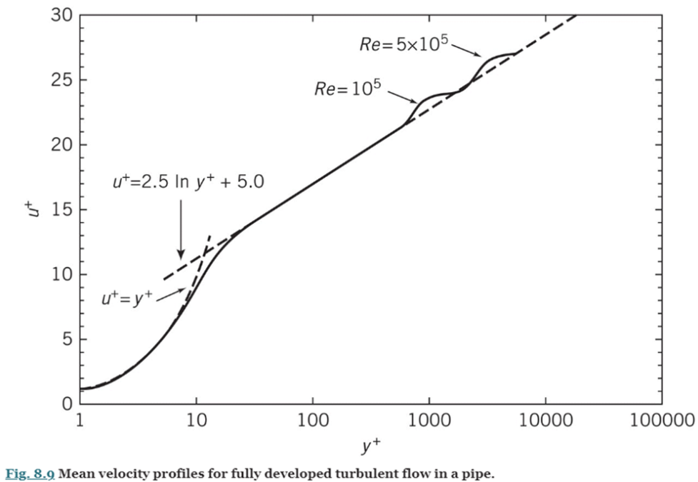
The velocity profile data for turbulent pipe flow from a large number of investigators is plotted in Fig. 8.9 on semi-logarithmic coordinates. In the region very close to the wall where viscous shear is dominant, called the viscous sublayer, the mean velocity profile follows the linear relation given by Eq .1 up to about
Surprisingly, the model proposed by Prandtl nearly 100 years ago has proved valuable in understanding and analyzing turbulent flows. If Eq. 2 is evaluated at the centerline (
where
Internal incompressible viscous flow
where
is a Kinetic Energy Coefficient. Then the Major Losses: Friction Factor
- In Laminar Flow
- Turbulent Flow
where
Thus:
where
And Colebrook
Minor Losses:
See Internal Flow about laminar and turbulent flows in pipes as well as minor losses, for more details.
External incompressible viscous flow
Drag:
- Pure Friction Drag: Flow over a Flat Plate Parallel to the Flow
- Pure Pressure Drag: Flow over a Flat Plate Normal to the Flow
Lift:
where
Example: Pipe flow into a reservoir
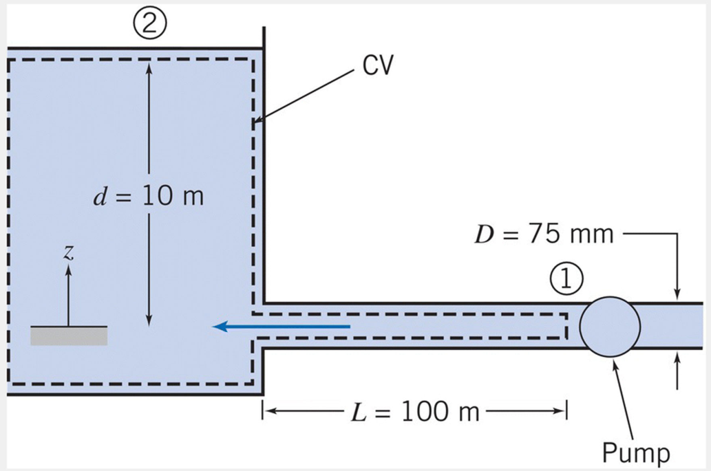
A 100-m length of smooth horizontal pipe is attached to a large reservoir. A pump is attached to the end of the pipe to pump water into the reservoir at a volume flow rate of
Given: Water is pumped at
through a -diameter smooth pipe, with , into a constant-level reservoir of depth . Find: Pump pressure,
, required to maintain the flow. Solution: Governing equations:
where
and
For the given problem,
The left side of the equation is the loss of mechanical energy between points (1) and (2); the right side is the major and minor losses that contributed to the loss. Solving for the pressure drop,
Everything on the right side of the equation is known or can be readily computed. The flow rate
This in turn [assuming water at
For turbulent flow in a smooth pipe (
Hence,
Basic Concept about Two Phase Flow
Nature of multiphase flows
Two-phase flows
- Gas-liquid
- Gas-solid
- Solid-liquid
- Liquid-liquid
Phase change
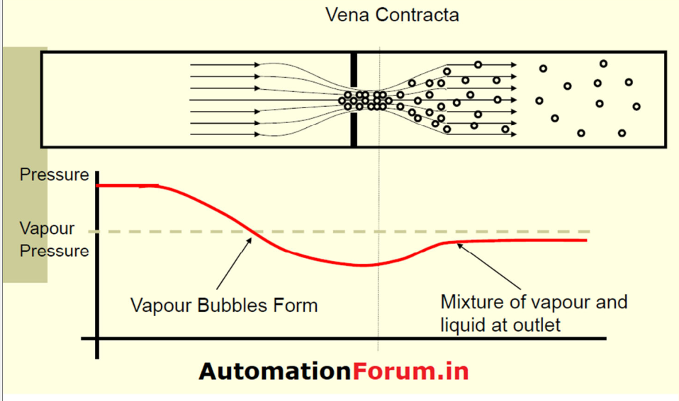
- Adiabatic: flashing (vaporization due to pressure changes)
- Diabatic: vaporization (boiling) or condensation
Orientation
- Vertical
- Horizontal
- Inclined
Flow direction
- Parallel or co-current flow
- Counter-current flow (e.g. falling liquid and rising gas)
Phenomena unique to multiphase flow:
- Critical heat flux
- Flow excursion
- Ledinegg instabilities
- Pressure drop
- Single-phase flow straightforward
- Two-phase flow: much more complicated
- Critical flows
- Single-phase flow: chocked at sonic velocity
- Two-phase flow: non-equilibrium
Application: air conditioner, nuclear reactor, thermal management, ...
The boiling curve:[core]
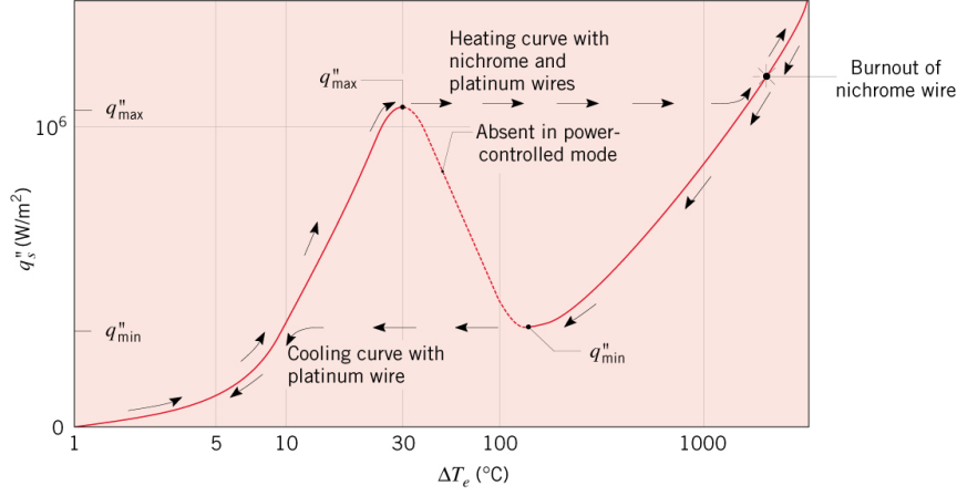
First slope(single phase flow, Newton laws of cooling):
Nature of multiphase flows and basic concepts
Introduction to Multiphase Flow
Definition: Phase
A phase is a thermodynamic definition for the state of the matter, which can be either solid, liquid or gas; these can co-exist in a conduit. Examples of multiphase flows are abundant, e.g. when oil is produced, one normally gets oil, water, gas and sand flowing in the pipelines (three-phase flow).
Definition: mixture
The term mixture is most of the time used to denote the two (or more) phases flowing together and does not necessarily imply that these are intimately mixed. For example, in the case of annular flow that we will introduce below, we may still refer to the flow as the two-phase mixture in spite of the fact that the liquid film on the wall and the gaseous core are not at all “mixed”. The term “separated flow” is often used loosely to denote two-phase flows where the two phases have different average velocities. This distinguishes such flows from the homogeneous ones, where the phases have the same average velocity; again, such flows may strictly speaking not be homogeneous at all. For example, bubbly flow with fairly large bubbles can be considered as homogeneous.
Definition: component
A component, is a chemical species. So, the term two-component is used to describe the flow of two chemical species. A water–steam mixture is two-phase, one-component, while a water–air mixture is two-phase, two-component flow; a water–oil mixture is one-phase, two-component, etc. The approach in modelling of the two alternative two-phase configurations—with one or two components—is often the same or very similar, though the physical behaviour of different mixtures may be quite different.
Definition: field
The term field is used to denote a topologically distinct or clearly identifiable fraction of a phase. For example, in the so-called annular flow, the liquid can be present as either a film on the wall or as droplets in the core where the gas flows; the droplets and the film can be considered as different fields. In a closed vessel such as a pressure cooker containing boiling water, we may define a field of steam bubbles in the liquid and a field of steam in the space above the liquid surface as separate fields.
Averaging in two-phase flow
- Local instantaneous quantity
- Local time-averaged quantity
- Instantaneous space-averaged quantity
- Time and space-averaged quantity
- Space averaging: Line, area, and volume-averaging
Key parameters in two-phase flow [core]
Void fraction 空隙率
- Local instantaneous void fraction (0 or 1)
- Instantaneous (volume, area, or line)-averaged void fraction (0-to-1)
- Time-averaged local void fraction (0-to-1)
- Time and (volume, area, or line)-averaged void fraction (0-to-1)
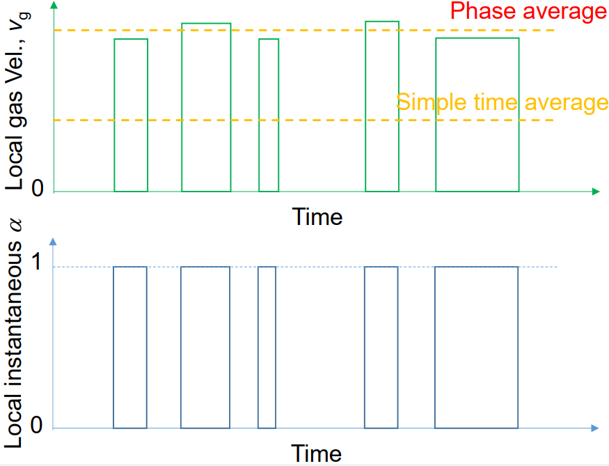
Phase velocity
- Instantaneous local gas (or liquid) velocity
- Phase-averaged local gas (or liquid) velocity
- Phase fraction weighted mean gas or liquid velocity
- Superficial gas or liquid velocity
Void fraction weighted mean (time-averaged) actual gas velocity (气相速度):
Area (and time)-averaged superficial gas velocity (表观气相速度) (volume center velocity):
where
Flow quality
- Mass velocity (or mass flux 质量通量) of
-phase, (Mass flow rate, [kg/s])
- Mass flowrate quality (or quality 流动干度),
[-]
- Superficial gas velocity,
and
- Volume flowrate quality,
(Mixture volumetric flux, [m/s])
When HEM(homogeneous) is assumed,
Mixture density (两相混合物密度)
- Assumption: Perfectly mixed gas and liquid phases with the same velocity (homogeneous flow),
( : specific volume, : density)
- Specific volume of mixture
- Mixture density
With different velocity:
- Mixture density:
- Mixture velocity (Mass center velocity)
Summary
- Void fraction
- Interfacial area concentration (界面面积浓度)
- Bubble number density
- Energy dissipation rate per unit mass
- Superficial
-phase velocity
- Reynolds number
- Bubble Reynolds number
- Quality
-phase velocity
Fundamental equations for separated two-phase flow
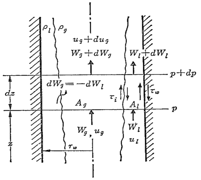
Objective: Derive area-averaged (1D) mass and momentum balance equations
Assumptions: Constant flow area, heated wall, two phases flowing separately
- Mass flow rates
phase velocity x Density x Flow area
- 1D Mass conservation equation (Continuity equation)
- Physical meaning: Phase change may change
. However, total mass flow ratte at the elevation is unchanged by the phase change
- Physical meaning: Phase change may change
1D Momentum
conservation equation - For gas phase
- For liquid phase
Further assumption: Uniform gas and liquid velocities over flow channel
Thus, Pressure change for total length
Axial changes of void fraction and wall shear stress should be known to calculate the total pressure loss.
Key components of one-dimensional two-phase flow analysis
- Key two-phase flow parameters
- Void fraction
- Quality
- Phase velocity
- Superficial velocity
- Mixture density
- Mixture viscosity
- Key conservation equations
- Mass conservation equation (or continuity equation)
- Momentum conservation equation
- Energy conservation equation
- Key constitutive equations
- Flow regime map (or flow regime transition criteria)
- Void fraction
- Two-phase frictional pressure drop
- Heat transfer coefficient
Quiz1
- Which of the following is a key parameter in thermal-hydraulic analysis?
- Pressure
- All of the above
- Velocity
- Temperature
- In multiphase flow, what is considered a two-phase flow?
- All of the above
- Solid-liquid
- Gas-solid
- Gas-liquid
- Which of the following types of flow is characterized by both phases moving in the same direction?
- Co-current flow
- Circular flow
- Counter-current flow
- Parallel flow
- What does "void fraction" measure in a two-phase flow system?
- Volume of gas
- Density of the mixture
- Ratio of gas volume to total volume
- Volume of liquid
- Which phenomenon describes vaporization due to pressure changes?
- Boiling
- Condensation
- Freezing
- Flashing
- What is the primary goal of a flow regime map?
- To calculate pressure drop
- To identify flow patterns
- To measure temperature
- To analyze velocity
- What does the term "superficial velocity" refer to?
- Velocity at which phase changes occur
- Actual velocity of the phase
- Average velocity of the mixture
- Velocity based on cross-sectional area
- What unique phenomenon can occur during multiphase flow?
- Critical heat flux
- Steady flow
- Laminar flow
- Turbulent flow
- In multiphase flow, what does "quality" represent?
- Density of the mixture
- Temperature difference
- Ratio of vapor mass velocity to total mixture mass velocity
Ratio of vapor to liquid
- Which of the following is NOT a type of two-component two-phase flow?
- Air-water
- None of the above
- Steam-water
- Nitrogen-liquid metal
- What is a typical characteristic of two-phase flow pressure drop?
- More complicated than single-phase flow
- Simple compared to single-phase flow
- Constant across all conditions
- Irrelevant in multiphase systems
- Which factor significantly influences the void fraction in a two-phase flow?
- Temperature
- All of the above
- Flow rate
- Phase densities
- What is the typical outcome of using a homogeneous flow assumption?
- Increased pressure drop
- Reduced flow rate
- Same velocity for gas and liquid phases
- Different velocities for phases
- What type of pressure loss is associated with the liquid phase in a two-phase flow?
- Hydrostatic pressure loss
- Acceleration loss
- Frictional pressure loss
- All of the above
- What does the term "bubble Reynolds number" measure?
- Pressure drop in the system
- Viscosity of the liquid
- Velocity of the gas phase
- Drag coefficient
- Which of the following flow regimes is characterized as separated flow?
- Slug flow
- Bubbly flow
- Annular flow
- Churn flow
- What does void fraction=1 mean?
- Liquid single-phase flow
- Same velocity for gas and liquid phases
- Same volume fraction for gas and liquid phases
- Gas single-phase flow
- What is the volume flowrate quality value for superficial gas velocity=1 m/s and superficial liquid velocity 0.5 m/s?
- 0.67
- 2
- 0.5
- 1
Why:
- What is the void fraction value for gas velocity=1 m/s and superficial gas velocity 0.5 m/s?
- 1
- 2
- 0.67
- 0.5
- What does the term "interfacial area concentration" refer to?
- Volume of dispersed phase
- Ratio of interfacial area to total volume
- Total surface area of the phases
- Density of gas and liquid