3 External Flows and Boundary Layers
Introduction
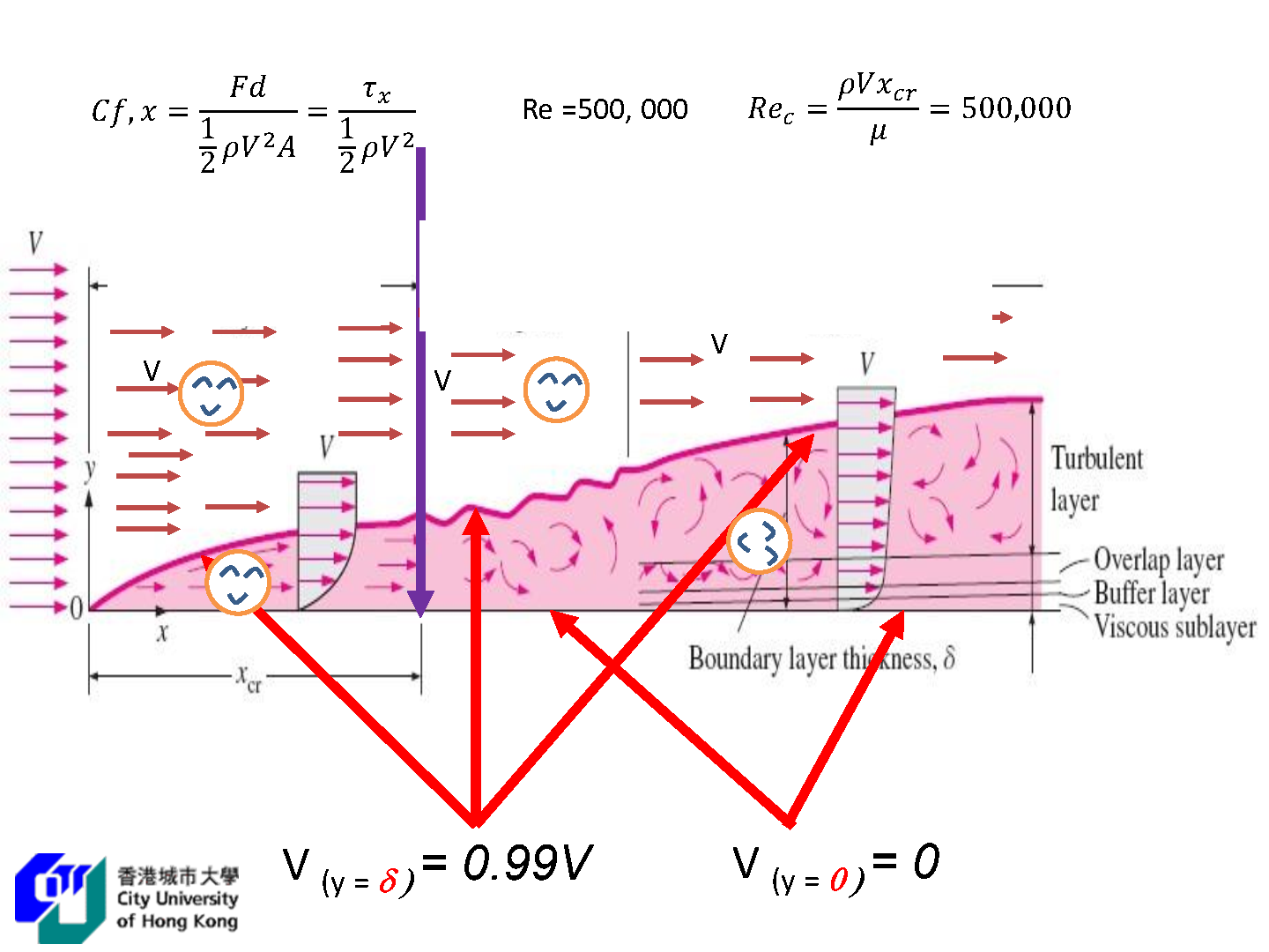
Definition: Velocity boundary layer
The region of the flow above the plate bounded by
The boundary layer thickness
- Boundary layer region: The viscous effects and the velocity changes are significant (rotational flow region).
- Irrotational flow region: The frictional effects are negligible and the velocity remains essentially constant.
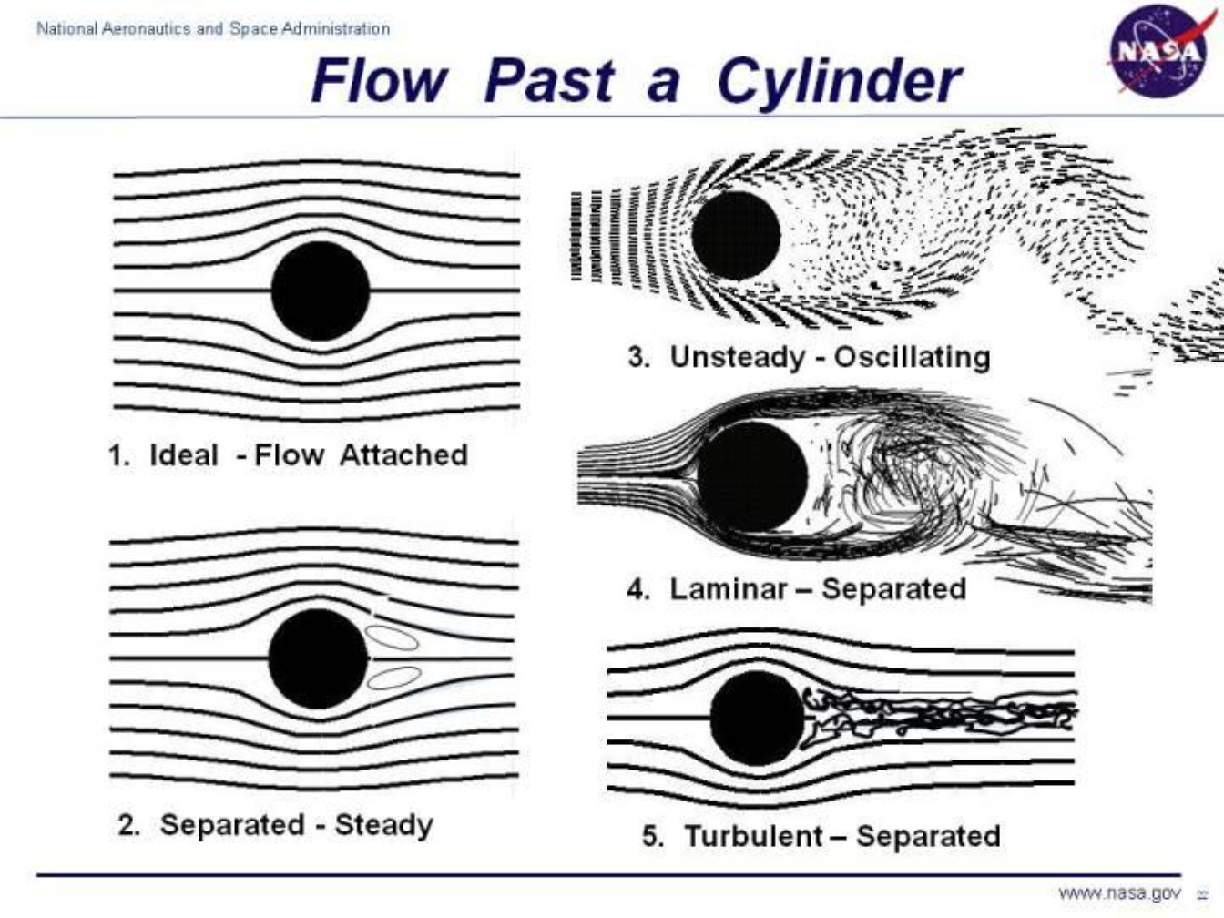
Boundary layer determines separation point
Quiz: For flow over a smooth flat plate. The transition from laminar to turbulent flow occurs when the Reynolds number is about:
500,000
Quiz: Define the friction coefficient
Quiz: Define the Reynolds number for flow over a flat plate
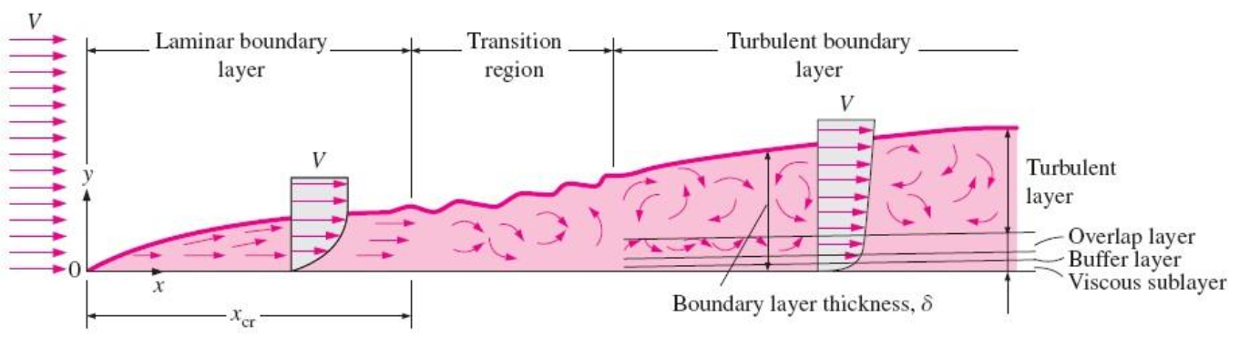
The turbulent boundary layer can be considered to consist of four regions, characterized by the distance from the wall:
- viscous sublayer
- buffer layer
- overlap layer
- turbulent layer
The development of a boundary layer on a surface is due to the no-slip condition and friction
The transition from laminar to turbulent flow depends on the surface geometry, surface roughness, upstream velocity, surface temperature, and the type of fluid, among other things, and is best characterized by the Reynolds number.
The Reynolds number at a distance
: length of plate in the flow direction - For flow over a smooth flat plate, transition from laminar to turbulent begins at about
, but does not become fully turbulent before the Reynolds number reaches much higher values, typically around . - depending on the surface roughness, the turbulence level, and the variation of pressure along the surface
- In engineering analysis, a generally accepted value for the critical Reynolds number is
.
Quiz: What is the criteria for the boundary layer thickness?
Quiz: The flow inside the boundary layer region is rotational (T/F?)
True
Quiz: The flow outside the boundary layer region is rotational (T/F?)
False
Friction Coefficient:
- The friction coefficient for laminar flow over a flat plate can be determined theoretically by solving the conservation of mass and momentum equations numerically.
- For turbulent flow, it must be determined experimentally and expressed by empirical correlations.
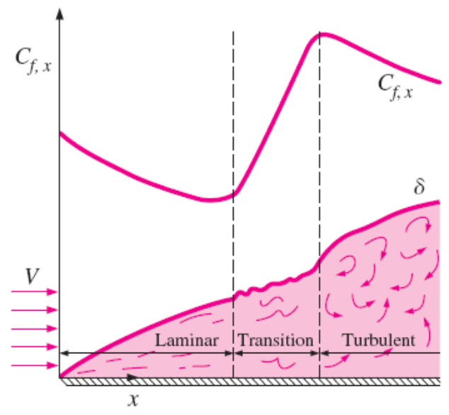
The variation of the local friction coefficient for flow over a flat plate. Note that the vertical scale of the boundary layer is greatly exaggerated in this sketch.
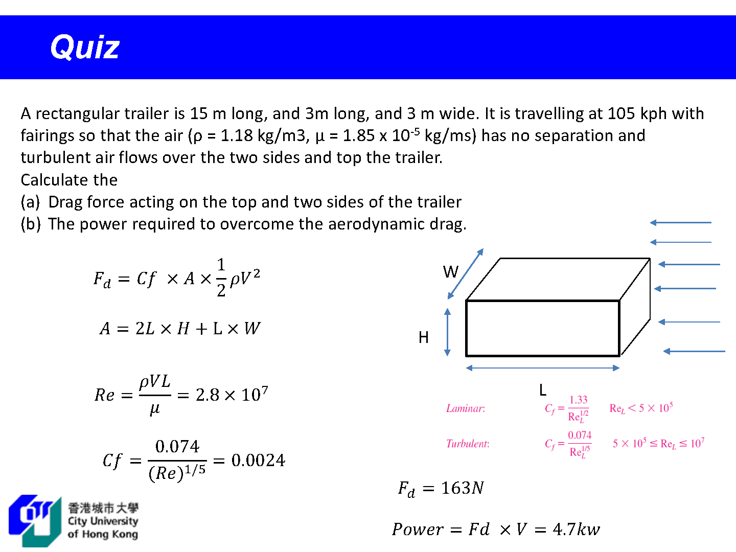
Laminar:
turbulent:
Laminar (Theory):
turbulent (Empirical):
Quiz: For laminar flow over flat plate, if the fluid-stream velocity is doubled (while the flow remains laminar) calculate the change in the viscous drag force on the plate.
Calculate the viscous drag force:
Flow Over Cylinders and Spheres
- Flow over cylinders and spheres is frequently encountered in practice.
- The tubes in a shell-and-tube heat exchanger involve both internal flow through the tubes and external flow over the tubes.
- Many sports such as soccer, tennis, and golf involve flow over spherical balls.
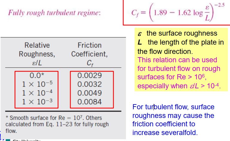
Impact of Roughness on drag
- For laminar flow, the friction coefficient depends only on the Reynolds number, and the surface roughness has no effect.
- For turbulent flow, surface roughness causes the friction coefficient to increase severalfold, to the point that in the fully rough turbulent regime the friction coefficient is a function of surface roughness alone and is independent of the Reynolds number.
- Surface roughness, in general, increases the drag coefficient in turbulent flow. This is especially the case for streamlined bodies.
- For blunt bodies such as a circular cylinder or sphere, however, an increase in the surface roughness may increase or decrease the drag coefficient depending on Reynolds number.
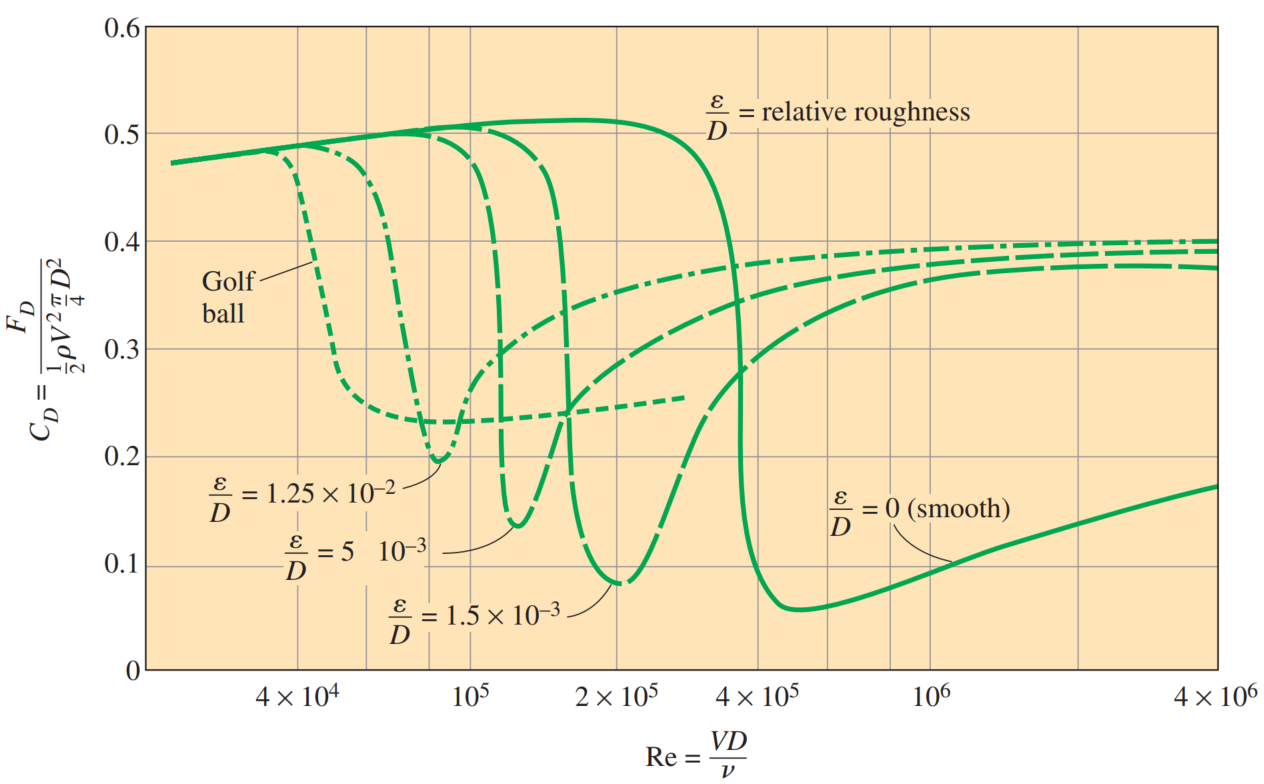
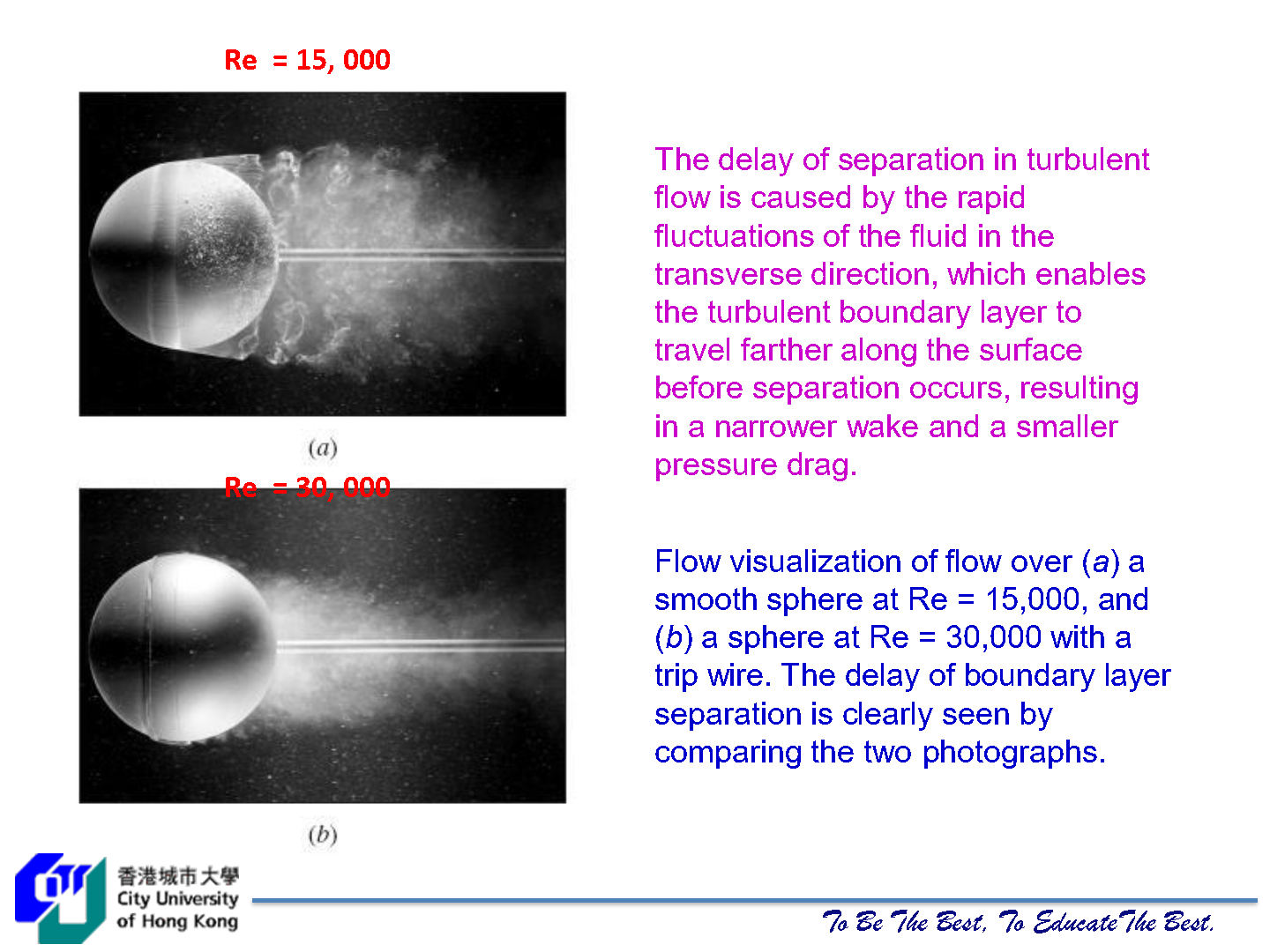
The effect of surface roughness on the drag coefficient of a sphere
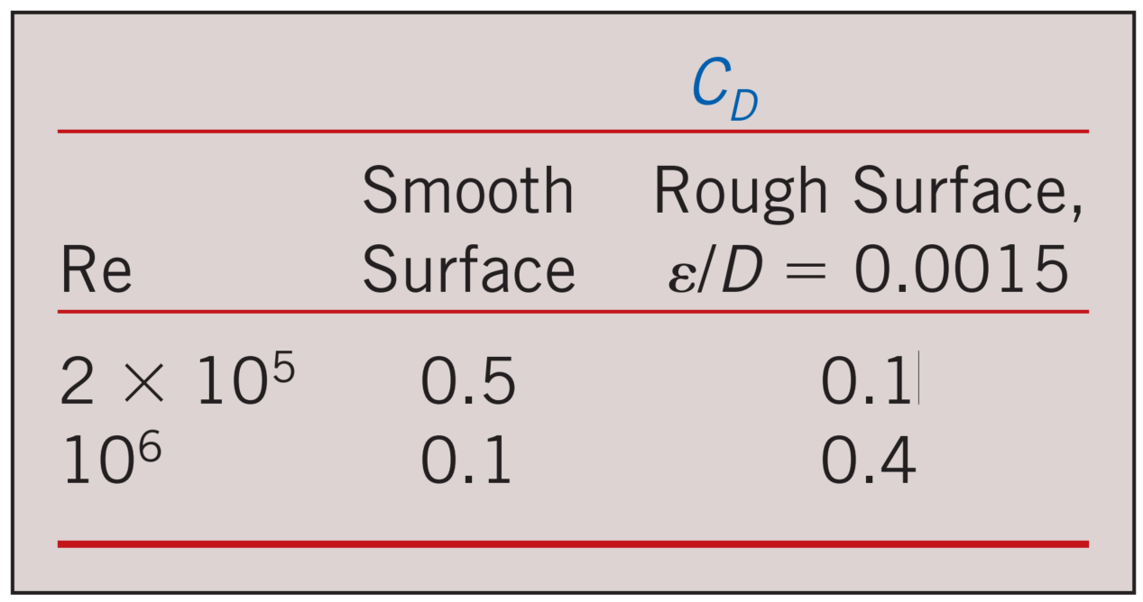
Surface roughness may increase or decrease the drag coefficient of a spherical object, depending on the value of the Reynolds number
Roughening the surface can be used to great advantage in reducing drag.
Golf balls are intentionally roughened to induce turbulence at a lower Reynolds number to take advantage of the sharp drop in the drag coefficient at the onset of turbulence in the boundary layer (the typical velocity range of golf balls is 15 to 150 m/s, and the Reynolds number is less than
For a table tennis ball, however, the speeds are slower and the ball is smaller—it never reaches speeds in the turbulent range. Therefore, the surfaces of table tennis balls are made smooth.
Quiz: What is the purpose of dimpling on golf balls?
Increase the air pressure on the back-side of the ball
Quiz: Why aren’t dimples on surfaces of planes, cars or trucks?
Better to increase streamlining of planes, cars and trucks
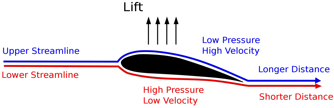
Lift
Definition: Lift
The component of the net force (due to viscous and pressure forces) that is perpendicular to the flow direction.
For an aircraft, the wingspan is the total distance between the tips of the two wings, which includes the width of the fuselage between the wings.
The average lift per unit planform area
- No air, no lift
- No motion, no lift
Angle of attack is the angle between a reference line on a body (often the chord line of an airfoil) and the vector representing the relative motion between the body and the fluid through which it is moving (wind v.s. airfoil)
Quiz: Pressure is at locations where the flow velocity is high , and pressure is high at locations where the flow velocity is low. (T/F?)
True
Quiz: At zero angle of attack, the lift produced by a symmetrical airfoil is zero
True
- Lift in practice can be taken to be due entirely to the pressure distribution on the surfaces of the body, and thus the shape of the body has the primary influence on lift.
- Then the primary consideration in the design of airfoils is minimizing the average pressure at the upper surface while maximizing it at the lower surface.
- For airfoils, the contribution of viscous effects to lift is usually negligible since wall shear is parallel to the surfaces and thus nearly normal to the direction of lift.
It is desirable for airfoils to generate the most lift while producing the least drag. Therefore, a measure of performance for airfoils is the lift-to-drag ratio, which is equivalent to the ratio of the lift-to-drag coefficients
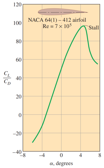
The
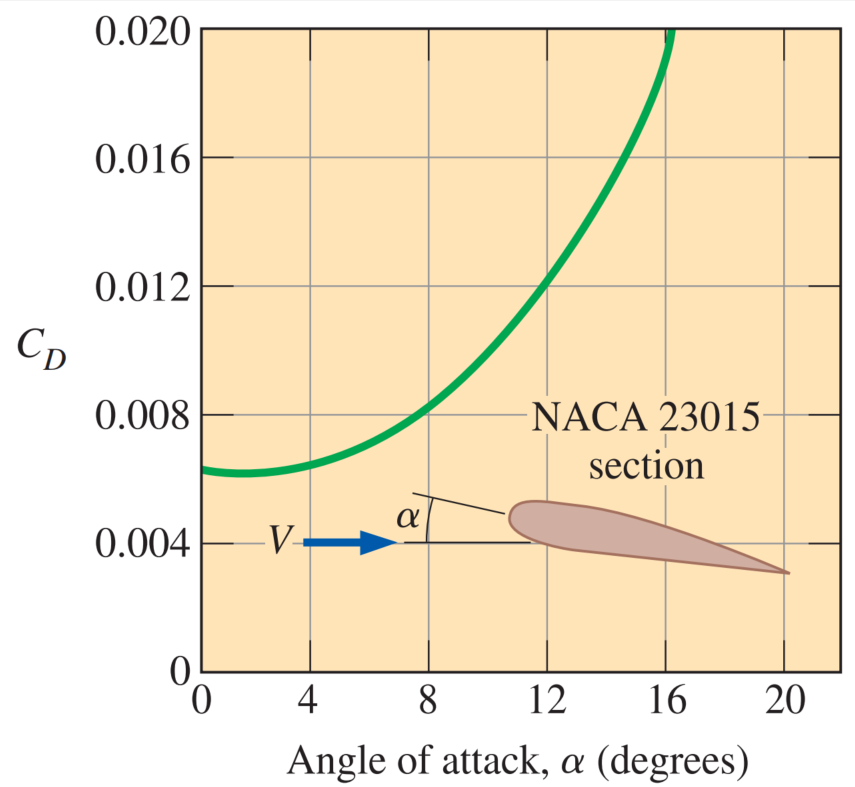
The drag coefficient increases with the angle of attack, often exponentially.
Therefore, large angles of attack should be used sparingly for short periods of time for fuel efficiency.
- One way to change the lift and drag characteristics of an airfoil is to change the angle of attack.
- On an airplane, the entire plane is pitched up to increase lift, since the wings are fixed relative to the fuselage.
- Another approach is to change the shape of the airfoil by the use of movable leading edge and trailing edge flaps.
The minimum flight velocity can be determined from the requirement that the total weight
For a given weight, the landing or takeoff speed can be minimized by maximizing the product of the lift coefficient and the wing area
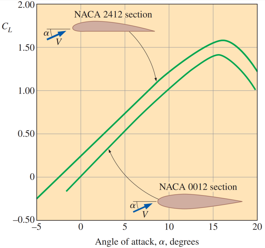
The variation of the lift coefficient with the angle of attack for a symmetrical and a nonsymmetrical airfoil.
increases almost linearly with the angle of attack , reaches a maximum at about , and then starts to decrease sharply. The lift coefficient can be increased severalfold by adjusting the angle of attack - At zero angle of attack (
), the lift coefficient is zero for symmetrical airfoils but nonzero for nonsymmetrical ones with greater curvature at the top surface. - Therefore, planes with symmetrical wing sections must fly with their wings at higher angles of attack in order to produce the same lift.
This decrease of lift with further increase in the angle of attack is called stall, and it is caused by flow separation and the formation of a wide wake region over the top surface of the airfoil. Stall is highly undesirable since it also increases drag.
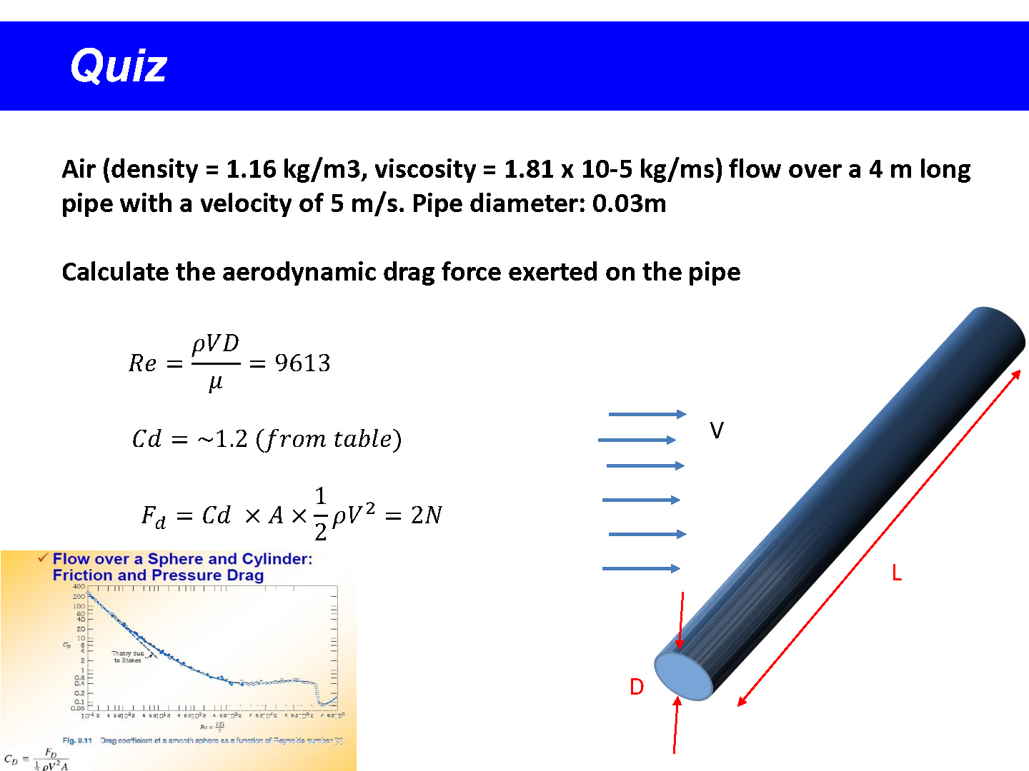
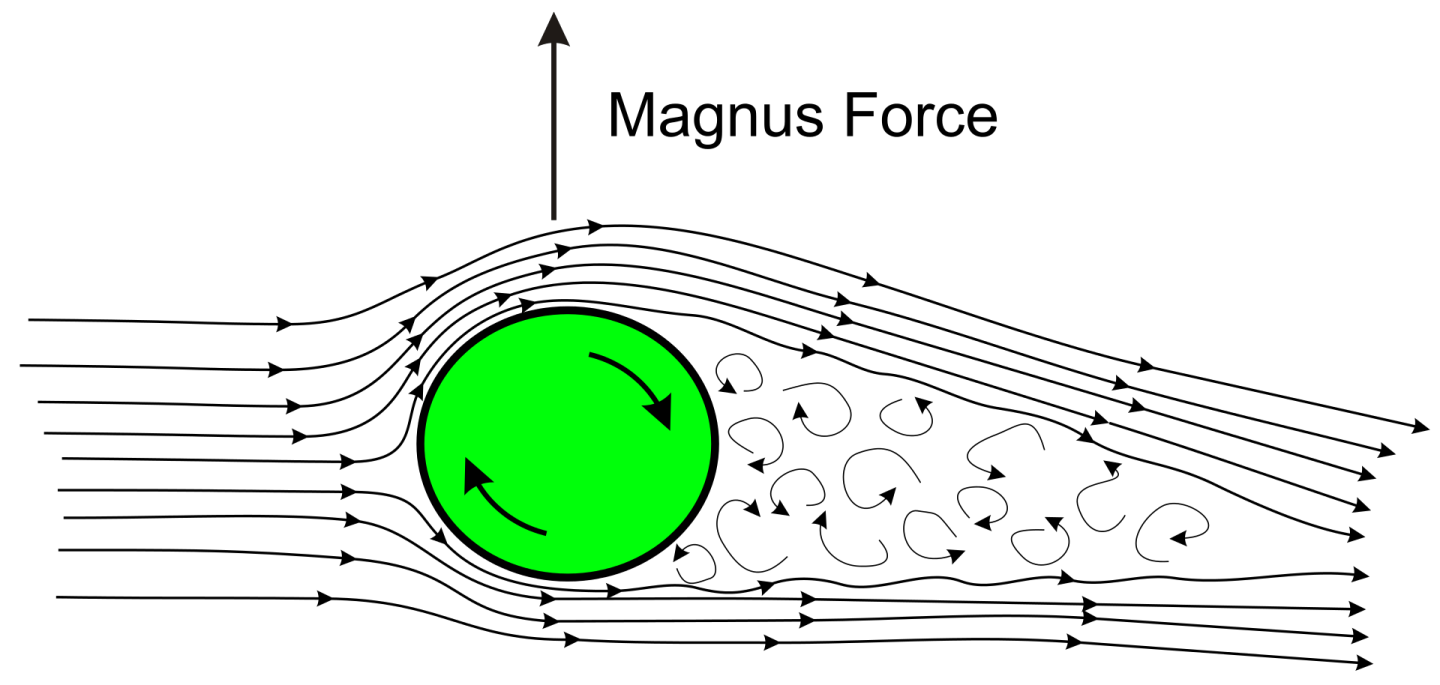
Example Problem
GIVEN: Tennis ball in flight, with
FIND: (a) Aerodynamic lift acting on ball. (b) Radius of curvature of path in vertical plane. (c) Comnarison with radius for no soin.
SOLUTION:
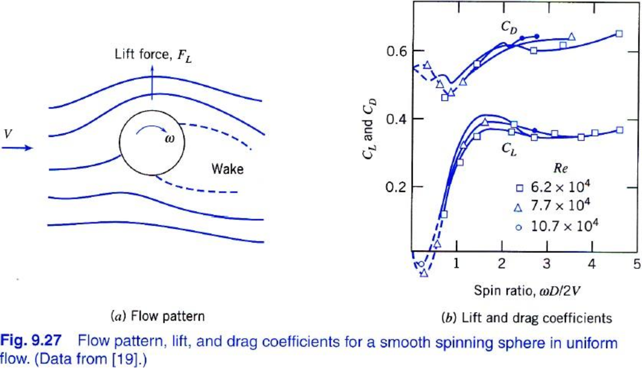
Assume ball is smooth. Use data from Fig. 9.27 to find lift:
From Fig. 9.27,
Because the ball is hit with topspin, this force acts downward. Use Newton's second law to evaluate curvature of path. In the vertical plane,
Thus topspin has a significant effect on trajectory of the shot!