
Sensors for Robotics and Control Systems
Introduction
Robot - a machine resembling a human being and able to replicate certain human movements and functions automatically.
- Move – Perception of the environment, sensing its position
- Functions – Manipulation: assembly, welding, painting, rescuing…
Sense of human:
- Vision
- Hearing
- Smell
- Taste
- Touch
Sensors for Robotics
- Force and Tactile Sensing – Manipulation of object
- Position Sensing – Perception of the environment
- Inertial Sensing, GPS
- Sonar Sensing
- Range Sensing
- Vision – Seeing is believing
- 3-D vision
- Visual Servoing
- Multi-sensor data fusion
Force and tactile
- How important is tactile sensing? In nature, tactile sensing is an essential survival tool
- What is it useful for?
- Manipulation – button a shirt/ perform surgery
- Exploration – feeling object, touch the surface
- Response – gentle touch, safe response
- Why does it remain comparatively undeveloped? vs. Vision
Mechanoreceptors per square centimeter of skin
- mechanical signal to electrical
- pressure, touch, vibration, and stretch
touch receptors; - 2 to 3 millimeters sensing resolution
- Uneven distribution
- tactile sensors elicit information through physical interaction.
- They must be incorporated into skin surfaces with compliance, for conforming locally to surfaces, and with adequate friction for handling objects securely.
Force sensor types
- The most important quantities measured with tactile sensors are shape and force
- Proprioceptive Sensing (‘the six sense’)
- perceive posture, movement, and joint positions without visual input
- for humans, proprioceptors are located within muscles, joints, and tendons
- the primary source for spatial proprioceptive information on a robot is provided by joint angle and force–torque sensors.
- joint angle sensors such as potentiometers, encoders, and resolvers are well established technologies
Joint angle sensors
Potentiometers
- adjustable voltage divider
Encoder
Rotary encoder
- A rotary encoder, also called a shaft encoder, is an electro-mechanical device that converts the angular position or motion of a shaft or axle to analog or digital output signals.
two main types of rotary encoder:
- absolute encoder indicates the current shaft position.
- incremental encoder provides information about the motion of the shaft, which typically is processed elsewhere into information such as position, speed and distance.
Electromechanical: Also known as conductive encoders.
- Magnetic: uses a series of magnetic poles (2 or more) to represent the encoder position to a magnetic sensor (typically magnetoresistive or Hall Effect). The magnetic sensor reads the magnetic pole positions.
- Optical: uses a light shining onto a photodiode (photoelectric) through slits in a metal or glass disc. Reflective versions also exist.
This is one of the most common technologies.
Encoding:
- Standard binary encoding: 000-111: 0-360
Gray encoding - also known just as reflected binary (RB) or Gray code after Frank Gray, is an ordering of the binary numeral system such that two successive values differ in only one bit (binary digit).
| sector | Contact 1 | Contact 2 | Contact 3 | Angle |
|---|---|---|---|---|
| 0 | ||||
| 1 | ||||
| 2 | ||||
| 3 | ||||
| 4 | ||||
| 5 | ||||
| 6 | ||||
| 7 |
The binary-reflected Gray
- 2-bit: 00, 01, 11, 10
- 3-bit: 000, 001, 011, 010, 110, 111, 101, 100
- (1st 4 numbers: 0-(2-bit)), (last 4 numbers: 1-(2-bit in reverse form))
Signals:
- A rotary incremental encoder has two output signals, A and B, which issue square waves when the encoder shaft rotates.
- The square wave frequency indicates the speed of shaft rotation, whereas the A-B phase relationship indicates the direction of rotation.
Resolver
A resolver is a type of rotary electrical transformer used for measuring degrees of rotation.
The most common type of resolver is the brushless transmitter resolver.
The stator houses three windings: an exciter winding and two two-phase windings (usually labeled "x" and "y").
- The exciter winding is in fact a coil of a turning (rotary) transformer.
- The two other windings are configured at 90 degrees from each other.
Hall sensors
- The Hall effect is the production of a voltage difference (the Hall voltage) across an electrical conductor, transverse to an electric current in the conductor and to an applied magnetic field perpendicular to the current. It was discovered by Edwin Hall in 1879.
- The Hall effect is due to the nature of the current in a conductor. When a magnetic field is present, the electrical charges experience a force, called the Lorentz force.
- A particle of charge
moving with a velocity in an electric field and a magnetic field experiences a force of
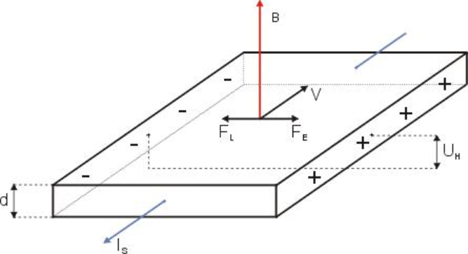
: Hall Voltage. The potential difference generated across the conductor. : Electric Force. The force exerted on the charge carriers by the induced Hall electric field. : Magnetic Force (Lorentz Force). The force exerted on the moving charge carriers by the external magnetic field. : Elementary Charge. The charge of a single carrier (e.g., the charge of an electron). : Drift Velocity. The average velocity of the charge carriers moving through the material. : Magnetic Field Density. The strength of the external magnetic field applied perpendicularly to the current. : Current Density. The electric current per unit area of the cross-section. : Supply Current. The external electrical current flowing through the sensor. : Width. The width of the conductive material (the distance across which the Hall voltage is measured). : Thickness. The thickness of the conductive material. : Charge Carrier Density. The number of charge carriers per unit volume of the material.
Whisker and Antenna Sensors~
whiskers or antennae provide an accurate combination of contact sensing and proprioceptive information
Proximity Sensors
- Capacitive sensors
- Capacitive proximity sensors are non-contact devices that can detect the presence or absence of virtually any object regardless of material. They utilize the electrical property of capacitance and the change of capacitance based on a change in the electrical field around the active face of the sensor.
- Inductive Sensors
- A inductive proximity sensor can detect metal targets approaching the sensor, without physical contact with the target.
- infrared (IR)
- An infrared sensor is an electronic instrument that is used to sense certain characteristics of its surroundings by either emitting or detecting infrared radiation.
- Infrared sensors are also capable of measuring the heat being emitted by an object and detecting motion.
- A passive infrared sensor (PIR sensor) is an electronic sensor that measures infrared (IR) light radiating from objects in its field of view. They are most often used in PIR-based motion detectors. PIR sensors are commonly used in security alarms and automatic lighting applications.
- An ultrasonic sensor
- An ultrasonic sensor is an instrument that measures the distance to an object using ultrasonic sound waves. An ultrasonic sensor uses a transducer to send and receive ultrasonic pulses that relay back information about an object's proximity.
- The ultrasonic sensor calculates the distance of the object from the speed of sound. When sound is propagated in air, the speed of sound is about
at room temperature
Force and Load Sensing
Force sensing for prosthetic hand
- There are many types of force sensors, usually referred to as torque cells (to measure torque) and load cells (to measure force).
Strain Gauge
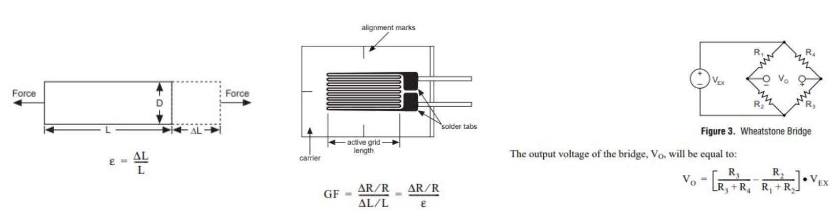
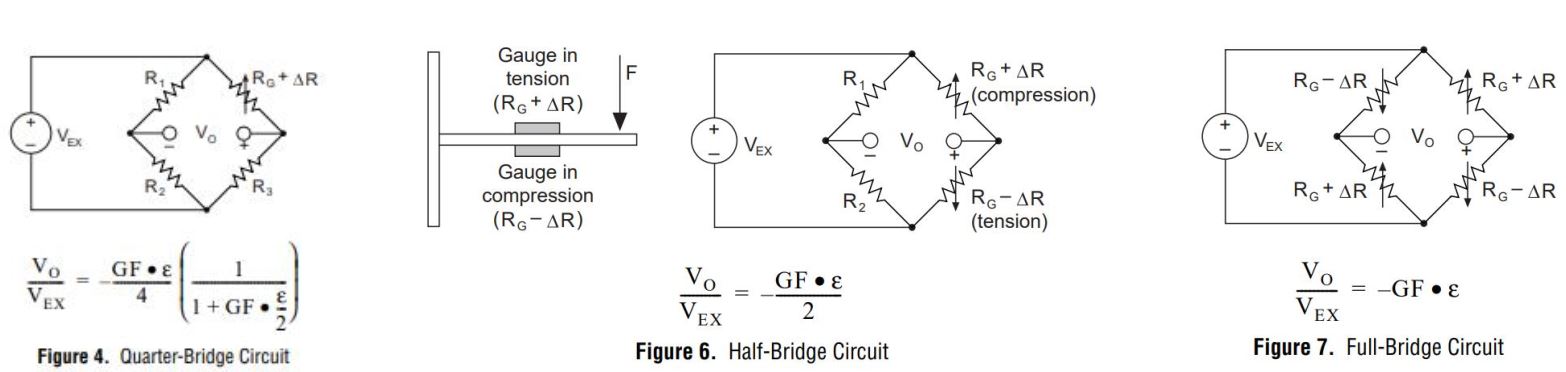
- Quarter-Bridge Circuit
- Half-Bridge Circuit
- Full-Bridge Circuit
FBG strain sensing
- A fiber Bragg grating (FBG) is a type of distributed Bragg reflector constructed in a short segment of optical fiber that reflects particular wavelengths of light and transmits all others.
- This is achieved by creating a periodic variation in the refractive index of the fiber core, which generates a wavelength-specific dielectric mirror.
- A fiber Bragg grating can therefore be used as an inline optical filter to block certain wavelengths, or as a wavelength-specific reflector.
Applications
Force sensing in medical robot: A Motorized Force-Sensing Microneedle for Robot-Assisted Retinal Vein Cannulation
Capacitive Force Sensor
- A force-sensing capacitor is a material whose capacitance changes when a force, pressure or mechanical stress is applied. They are also known as "force-sensitive capacitors".
- They can provide improved sensitivity and repeatability compared to force-sensitive resistors but traditionally required more complicated electronics.
How:
- Sensing
- Capacitance between moving and fixed plates change as
- Distance and position is changed
- Media is replaced
- Capacitance between moving and fixed plates change as
- Actuation
- Electrostatic force (attraction) between moving and fixed plates as
- A voltage is applied between the plates
- Electrostatic force (attraction) between moving and fixed plates as
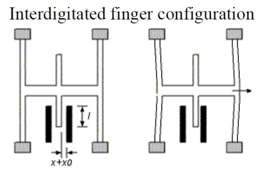
Parallel Plate Capacitor
Equations without considering fringe electic field
Notes:
- The fringe field is frequently ignored in first-order analysis
- It can nonetheless be important. Its effect can be captured accurately in finite element tools
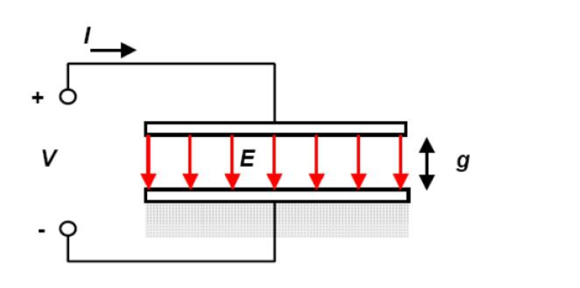
- Stored energy:
- Force is derivative of energy with respective to distance
We have the force expressed as:
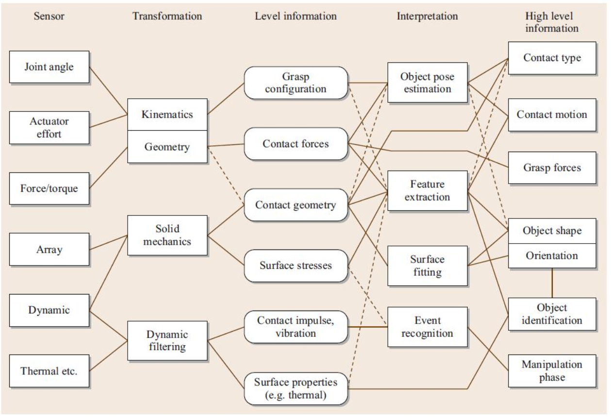
Force and tactile sensor information flow and signal processing
IMU
Introduction
- Mechanical Accelerometers:
- A mechanical accelerometer is essentially a spring-mass-damper system with some mechanism for external monitoring. When some force is applied (e.g., gravity), the force acts on the mass and displaces the spring.
Structure:
- Rather than relying on a direct mechanical measurement of external forces, piezoelectric accelerometers are based on a property exhibited by certain crystals which generate a voltage across them when stressed.
- Key component: A "proof mass" (with mass
) + a spring. - Principle analysis:
- At rest: The spring is at its natural length.
- Under acceleration: When the housing accelerates with
, the proof mass tends to remain at rest due to its inertia ( ), lagging relative to the housing, causing the spring to compress or extend. - Measurement: The spring deflection
is proportional to the acceleration . Measuring yields .
Gyroscopic Sensors – Mechanical System
- The goal of gyroscopic systems is to measure changes in vehicle orientation by taking advantage of physical laws that produce predictable effects under rotation.
- Gyroscopes and gyrocompasses rely on the principle of the conservation of angular momentum
- Angular momentum is the tendency of a rotating object to keep rotating at the same angular speed about the same axis of rotation in the absence of an external torque.
- Key component: A high-speed rotor (possesses large moment of inertia
). - Principle analysis:
- Rigidity in space (stability): When the rotor spins at high speed, its angular momentum
is large. According to the angular momentum theorem, a large external torque is required to change the direction of . Thus, the rotor axis remains stable in inertial space. - Application: In aircraft or missiles, the gyroscope rotor axis points toward a distant star. If the aircraft changes its attitude, the airframe rotates relative to the rotor axis. Measuring the relative angle gives the attitude.
- Precession (angular velocity measurement): If a torque
is deliberately applied, the rotor does not fall in the direction of the torque but precesses perpendicularly. Measuring the precession rate allows one to deduce the input angular velocity (principle of a rate gyroscope).
- Rigidity in space (stability): When the rotor spins at high speed, its angular momentum
| Feature | Translational Inertia (Mass | Rotational Inertia (Moment of Inertia |
|---|---|---|
| Definition Formula | ||
| Determinants | Depends only on the object itself (amount of matter) | Depends on mass distribution and axis position |
| Properties | 1. Scalar (no direction) 2. Intrinsic 3. Unique for an object | 1. Axis-dependent (same object, different axis → different 2. Additive 3. Larger when mass is farther from the axis |
| Conserved Quantity | Momentum | Angular Momentum |
| Resists Change in | Magnitude of linear velocity | Magnitude and direction of angular velocity |
Gyroscope
MEMS
An object moving in a straight line with local velocity
Optical system
- A fibre-optic gyroscope (FOG) senses changes in orientation using the Sagnac effect.
- The Sagnac effect, also called Sagnac interference, named after French physicist Georges Sagnac, is a phenomenon encountered in interferometry that is elicited by rotation.
- The FOG was first proposed by Vali and Shorthill in 1976.
- A FOG provides extremely precise rotational rate information
Conclusion
- As individual gyros only measure rotation about a single axis, it is common to group multiple gyros together with orthogonal axes of sensitivity in order to measure 3-D rotations.
- These collections of gyros are often integrated with other sensors (compasses, accelerometers, etc.) in order to construct inertial measurement units (or IMUs).
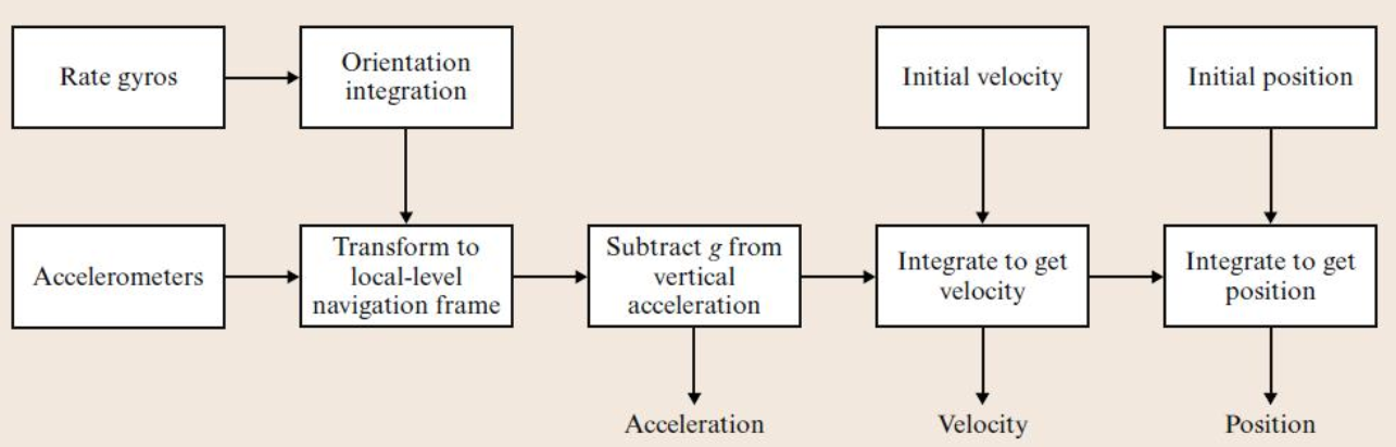
- IMU’s are extremely sensitive to measurement errors in the underlying gyroscopes and accelerometers (also accumulative!). As the accelerometer data is integrated twice, any residual gravity vector will result in a quadratic error in position
GPS
- The Global Positioning System (GPS), originally NAVSTAR GPS, is a satellite-based radionavigation system owned by the United States government and operated by the United States Space Force.
- It is one of the global navigation satellite systems (GNSS) that provides geolocation and time information to a GPS receiver anywhere on or near the Earth where there is an unobstructed line of sight to four or more GPS satellites.
- Obstacles such as mountains and buildings block the relatively weak GPS signals.
Other GNSS:
- GLONASS
- Galileo
- Beidou
GPS-IMU Integration
- It has become commonplace for GPS and IMU technologies to be integrated into a single GPS-aided inertial navigation system (GPS/INS).
- Although GPS offers positioning information on or about the surface of the planet, it does not solve all of the problems.
- it does not directly obtain information about vehicle orientation – to determine the orientation of the vehicle (yaw, and for many vehicles pitch and roll) must be estimated through integration with other sensors including compasses, gyrocompasses, and IMU’s.
- GPS receivers are generally unable to provide continuous independent estimates of position. Estimates are only available at distinct time instances with considerable delays between measurements.
- it is not always possible to obtain a GPS fix. Local geography (e.g., mountains, buildings, trees) or an overhead cover that is opaque to radio signals (e.g., indoors, underwater) can block the signal entirely.
- Integration of a GPS receiver with other sensor technology (often an IMU) can be used to deal with these issues, at least for short periods of time.