Introduction to Electrostatic (Capacitive) Sensors
Introduction to MEMS Transduction Principles
Micro-Electromechanical Systems (MEMS) are fundamentally defined by their ability to perform transduction—the conversion of energy between the physical and electrical domains. For engineers, this necessitates a rigorous understanding of how external physical stimuli are converted into measurable electrical signals (sensors) and how electrical inputs are leveraged to generate controlled mechanical motion (actuators).
In modern micro-scale engineering, 4 primary physical principles dominate:
- Piezoelectric: Stress-induced polarization in specific crystal structures.
- Thermal: Exploiting differences in thermal expansion coefficients to produce displacement.
- Magnetic: Utilizing Lorentz forces or magnetic attraction, often requiring complex integration of coils or permanent magnets.
- Capacitive (Electrostatic): Leveraging the interaction between stored charge and electrode geometry.
However, these principles can also be used to transduce external input into electrical output
Why it Matters: The Versatility of the Capacitive Method The capacitive method is arguably the most ubiquitous in commercial MEMS. Unlike piezoelectric or thermal methods, it requires no "smart" or exotic materials; it can be implemented using standard structural materials like polysilicon or aluminum. Furthermore, capacitive devices exhibit exceptionally low power consumption (being voltage-driven rather than current-driven) and provide a high-fidelity mechanical-to-electrical response. While the operational distance is limited, the scaling benefits at the micro-level make it the gold standard for high-speed, high-precision sensing and actuation.
Ferroelectrics and the Piezoelectric Effect
Piezoelectricity is a property of non-centrosymmetric materials where mechanical stress induces electric polarization. To master these materials, one must understand the hierarchy of properties:
All ferroelectrics (铁电材料) are pyroelectric (热电) and therefore piezoelectric.
- Examples of materials that are piezoelectric but not ferroelectric: quartz (
), ZnO, AlN. - Examples of Ferroelectric materials (and thus piezoelectric):
, PZT, PVDF (in certain phases).
This nested relationship is critical for material selection in sensor design.
Material Classification
- Piezoelectric (Non-Ferroelectric): Materials such as Quartz (
), Zinc Oxide (ZnO), and Aluminum Nitride (AlN). These lack switchable domains but are highly stable for frequency control. - Ferroelectric (and Piezoelectric): Materials like Barium Titanate (
), Lead Zirconate Titanate (PZT), and Polyvinylidene fluoride (PVDF). These possess a spontaneous polarization that can be reversed by an external field.
The Direct and Converse Effects: The Direct Effect involves generating an electric displacement (
Mathematical Modeling of Voltage Generation In a sensing application, the voltage (
(Conversely, if a voltage is applied across a structure made of a piezoelectric material, a displacement will occur on the structure due to
generate across the material.)
Technical Note: Dimensionally, the thickness
Practical Application: Quartz resonators remain the most common application of this principle, with approximately 10 million units produced daily. These single-crystal devices are vacuum-packaged and valued for their high Q-factor in timing circuits.
Fundamentals of Electrostatic (Capacitive) Sensing and Actuation
Electrostatic devices operate as variable capacitors. The sensing mechanism relies on the fact that capacitance (
Actuation: electrostatic force (attraction) between moving and fixed plates as a voltage is applied between them.
2 major Configurations:
- Parallel Plate capacitor: Typically used for out-of-plane (vertical) motion.
- Interdigitated Fingers / IDT: Commonly called "comb drives," these are designed for in-plane motion.
Relative Merits
- Pros: Universal sensing/actuation without special materials; ultra-low power; high speed (limited only by mechanical response and charging time).
- Cons: Inverses scaling (force
), vulnerability to particles in small gaps, and susceptibility to stiction (sticking due to molecular forces).
Parallel Plate Capacitor
Mathematical Analysis
For a parallel plate with area
Note:
Equations without considering fringe electric field.
- The fringe field is frequently ignored in first-order analysis. It is nonetheless important. Its effect can be captured accurately in finite element simulation tools.
Stored energy:
Force is derivative of energy w.r.t. pertinent dimensional variable
Plug in the expression for capacitor:
Arrive at the expression for force:
Relative Merits
Relative Merits of Capacitor Actuators: Pros:
- Nearly universal sensing and actuation; no need for special materials.
- Low power. Actuation driven by voltage, not current.
- High speed. Use charging and discharging, therefore realizing full mechanical response speed.
Cons:
- Force and distance inversely scaled - to obtain larger force, the distance must be small.
- In some applications, vulnerable to particles as the spacing is small - needs packaging.
- Vulnerable to sticking phenomenon due to molecular forces.
Analysis of Electrostatic Actuator
What happens to a parallel plate capacitor when the applied voltage is gradually increased?
The Electromechanical Model
An electrostatic actuator is a competitive system between non-linear electrical forces and linear mechanical restoring forces.
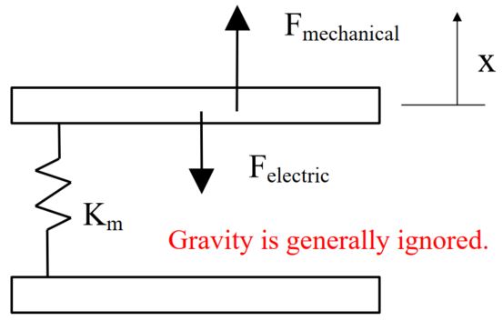
Equilibrium and Hooke’s Law: The suspension acts as a spring with a mechanical spring constant
Force Balance Equation at Given Applied Voltage
Design Implications: The "First Root" Rule The displacement can be found by solving the third-order equation:
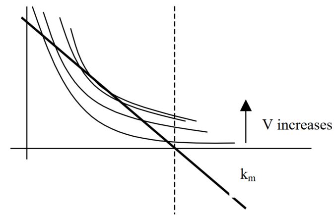
Determining Equilibrium Position Graphically:
- At each specific applied voltage, the equilibrium position can be determined by the intersection of the linear line and the curved line.
- For certain cases, two equilibrium positions are possible. However, as the plate moves from top to bottom, the first equilibrium position is typically assumed.
- Note that one curve intersects the linear line only at one point.
- As voltage increases, the curve would have no equilibrium position.
- This transition voltage is called pull-in voltage.
- The fact that at certain voltage, no equilibrium position can be found, is called pull-in effect.
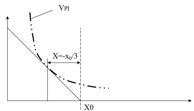
The "Pull-In" Effect
Definition: pull-in / snap in effect
As the voltage bias increases from
Mathematical Determination of Pull-in Voltage: Defining Electrical Force Constant Let’s define the tangent of the electric force term. It is called electrical force constant,
When voltage is below the pull-in voltage, the magnitude of
Key Takeaway:
- Reliable tuning is limited to only
of the total gap. Once the plates reach of the original spacing (a displacement of ), positive feedback causes the plates to "snap" into contact. - Electrostatic micro mirrors: reduced range of reliable position tuning
- Electrostatic tunable capacitor
- Reduced range of tuning and reduced tuning range
- Tuning distance less than
, tuning capacitance less than .
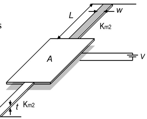
Example problem
A parallel plate capacitor suspended by 2 fixed-fixed cantilever beams, each with length, width and thickness denoted
. - The gap
between 2 plates is . - The plate area is
by .
Calculate the amount of vertical displacement when a voltage of
Find mechanical force constants
- Calculate force constant of one beam first: Under force
, the max deflection is . The force constant is therefore
- Total force constant encountered by the parallel plate is
.
- Calculate force constant of one beam first: Under force
Find out the Pull-in Voltage: Find out pull-in voltage and compare with the applied voltage.
- Find the static capacitance value
:
Find the pull-in voltage value- Find the static capacitance value
Hence, when the applied voltage is
What if the applied voltage is
Not sufficient to pull-in
Deformation can be solved by solving the following equation
or
Solving Third Order Equation To solve
: Apply , then and
.
others
Mechanical Spring:
- Cantilever beams with various boundary conditions
- Torsional bars with various boundary conditions
Example of MEMS system: Optical Micro Switches (MEMS Scanning Mirrors)
- Torsional parallel plate capacitor support
- 2 stable positions (+/- 10 degrees w.r.t. rest)
- All aluminum structure
- No process steps entails temperature above
Interdigitated Comb Drives and Accelerometers
Lateral vs. Transverse Drives
Lateral Comb Drives: Preferred for actuators because force is independent of displacement (as long as overlap is maintained). However, force is a function of finger thickness; thicker fingers yield higher force.
Total capacitance is proportional to the overlap length and depth of the fingers, and inversely proportional to the distance.
- Pros:
- Frequently used in actuators for its relatively long achievable driving distance.
- Cons
- force output is a function of finger thickness. The thicker the fingers, the large force it will be.
- Relatively large footprint
- Pros:
Transverse Comb Drives: Preferred for sensing due to extreme sensitivity to small displacements, though they have limited travel. Direction of finger movement is orthogonal to the direction of fingers.
- Pros: Frequently used for sensing for the sensitivity and ease of fabrication
- Cons: not used as actuator because of the physical limit of distance.
Sensing Devices Based on Transverse Comb Drive: Analog Devices ADXL Accelerometer The ADXL series utilizes a polysilicon proof mass supported by cantilever beams.
Summary
Most common MEMS actuators operate with one of the following physical principles:
- Piezoelectric, Thermal, Magnetic, or Capacitive (Electrostatic)
- However, these principles can also be used to transduce external input into electrical output è SENSORS!
- Capacitive Sensing Principle is one of the most widely used method for commercial MEMS sensors
- Low current (i.e., low power consumption)
- Very good mechanical input to electrical output response
- However, measurable input range is relatively small (due to small operation distance of capacitive plates.)