
Test in the class
Hints for Final Exam
- Master HW & Exercise Problem & Class note
- Understand flow parameter definition
- e.g.
- e.g.
- Understand the assumption for HEM
- Understand the drift-flux model
, after area-averaging: where when HEM
- Understand Lockhart-Martinelli method
- Understand boiling curve
- Understand thermal-equilibrium quality
where
- vaporization due to phase change: boiling(liquid become gas)
- different flow: churn, annular
- assumption about drift-flux model:
- Continuum Assumption (continua rather than discrete particles)
- Mixture Momentum Equation (does not solve separate momentum conservation equations)
- Existence of Interfacial Slip (Relative Velocity)
- Thermodynamic Equilibrium Assumption (share the same pressure and temperature)
- Steam and water fluid compressibility is negligible.
- Void fraction change along the flow direction is negligible.
- neglect which pressure drop: Acceleration loss
- Chemical reactor utilize bubbly flow. Reason is mass transfer is important.
is high at around : - How many equations HEM consider: 3 equations (combine gas and liquid)
same diameter, where is the bubble number density - disadvantages about slip model comparing to drift-flux model:
- Definition:
may be zero or negative, not appropriate: counter-current flow, lead to sigularities - highly flow-regime specific
- Often exhibits discontinuities or unrealistic predictions at the boundaries of its intended use
- Often a purely empirical curve-fit with limited connection to first principles. It generally does not scale well with system parameters
- Definition:
Problem2: Drift-flux model
Use data to fit the line to obtain
and with certain
Problem 3: L-M Method
Test1: Flow Loop Design
It has been decided to conduct a two-phase flow experiment at the given void fraction and mass flux. During the experiment, there will be a pressure drop in the system due to the liquid single-phase flow and two-phase flow. Estimation of the pressure drop is essential to select right equipment such as pump. To select the pump, liquid flow rate and total head loss are required. In the current simplified example, the procedure for pump selection is reviewed.
Given Key Information
- Void fraction:
- Mass flux
- Pressure condition:
- Temperature condition:
- Diameter of the vertical pipe test section:
- Height of the vertical pipe test section:
- Diameter of the horizontal water piping system:
- Length of the horizontal water piping system:
- Liquid density:
- Gas density:
- Liquid dynamic viscosity
- Gas dynamic viscosity:
- Gravity acceleration:
- Air-water surface tension:
Design Procedure
Step
- Boundary conditions:
, Fluid system: Steam-water - Identify key flow parameters:
and - Total pressure drop in two-phase flow test section
- Hydrostatic Pressure Drop:
. - Frictional Pressure Drop:
- Hydrostatic Pressure Drop:
- Total pressure drop in single-phase flow piping section
- Frictional Pressure Drop:
- Valve Head Loss:
- Frictional Pressure Drop:
- Total pressure drop in flow loop & Find an appropriate pump in terms of pump head and pump flow rate
Assumptions
- Ignore the pressure loss in two-phase mixing section
- Ignore the pressure loss at the inlet and outlet sections
- Steam and water fluid compressibility is negligible.
- Void fraction change along the flow direction is negligible.
Q1-1
Write down the superficial gas and liquid velocity
Answer:
Q1-2
Express the void fraction
Answer:
Q1-3
Use results of question 1 and drift-flux model to write the quality
Answer:
not right
Q1-4
Consider dispersed gas-liquid two-phase flows in a vertical pipe of radius
where
(3) Calculate the distribution parameter using
Answer:
- Here
- Here:
- Thus
Q1-5
Calculate the chum drift velocity value given by
at the atmospheric flow condition. Fluid properties at the atmospheric condition: air and water densities are
Answer:
Q1-6
Calculate the quality for air water flow at void fraction of
Answer:
Q1-7
Use the calculated quality
Answer:
Q1-8
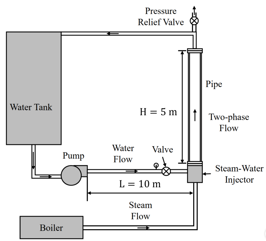
The figure shows the flow loop for the two-phase flow experiment in pipes. Water is driven by a pump and air is driven by an air compressor. They are mixed in the air-water injector, and then injected into the vertical pipe test section.
Assume that two phases flow in the vertical pipe with a diameter
Assume that the void fraction change along the flow direction is negligible.
Fluid properties are given by:
Answer: The two-phase hydrostatic pressure gradient is given by:
If the pipe height is
Q1-9
Following Question 4, calculate the two-phase frictional pressure gradient using the Lockhart-Martinelli method. What is the two-phase frictional pressure loss in the vertical pipe if the pipe length is
- Laminar flow:
- Turbulent flow:
Two-phase multiplier is given by:
where
| Liquid | Gas | C |
|---|---|---|
| Turbulent | Turbulent | 20 |
| Laminar | Turbulent | 12 |
| Turbulent | Laminar | 10 |
| Laminar | Laminar | 5 |
The answer should be given using
Answer: The relevant formulas:
The reynolds number about the liquid and gas are calculated by:
Both gas and liquid flows are turbulent. Thus, liquid and gas friction factors are calculated by:
Then, liuquid and gas pressure gradients are calculated by:
Then, the Lockhart-Martinelli coefficient is given by:
Eventually, we have
Q1-10
Assume that pipes for transporting water has the diameter (
Answer:
According to Question 7, the liquid velocity in the pipe test section is:
Then, the liquid volumetric flow rate is:
Then, the liquid velocity in the water pipe is:
Then, the liquid single-phase Reynolds number is:
The liquid single-phase flow is turbulent. Thus, the single-phase friction factor is:
Then, the liquid single-phase frictional pressure gradient is:
Then, the liquid single-phase frictional pressure loss is:
Q1-11
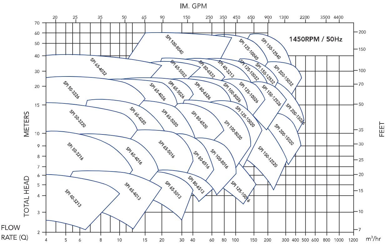
https://sppump.com/files/Superpower_In-Line_Pump_SPI_Series_.pdf#page=4.00
Assume that the total pressure loss from pump to the top of the test section consists of a pressure loss due to the horizontal single-phase liquid flow and a pressure loss due to the upward two-phase flow in the vertical test section. Use the values calculated in Questions 4 to 6 to obtain a total pressure loss. Then use the below chart to select a suitable pump. Hint: For pump selection, it is preferable to multiply the total estimated pressure loss by a factor
Answer:
The total pressure loss is equal to:
Required head loss is equal to:
pressure is converted to head (水头, height of liquid column in meters) using the formula
.
Required liquid flow rate is equal to:
Thus, the SPI 40-3213 is selected.
Test2: heat transfer
Liquid water with the mass flux
- Mass flux:
- Pressure condition:
- Inlet temperature condition:
- Saturation temperature:
- Diameter of the vertical pipe test section:
- Height of the vertical pipe test section
- Gravity acceleration:
Enthalpy of liquid water and steam:
- liquid enthalpy at inlet:
- Saturated liquid enthalpy:
- Saturated gas enthalpy:
- Latent heat:
Properties of saturatod water and steam:
- Saturated liquid density:
- Saturated liquid dynamic viscosity :
- Saturated liquad thermal conductivity:
- Saturated liquid isobaric heat capacity:
- Saturated gas density:
. - Saturated gas dynamic viscosity:
- Steam-water surface tension
- Steel-water contact angles
Typical boiling regime analysis
Step
- Flow boundary conditions: liquid water injected,
. Thermal boundary conditions: fixed heat flux or fixed wall temperature. Fluid system: steam-water. - Single-phase convection regime
- Subcooled nucleate boiling regime
- Onset of nucleate boiling (ONB)
- Onset of significant void (OSV)
- Saturated boiling regime
- Convective boiling heat transfer
- Nucleate boiling heat transfer
- Critical heat flux
Assumptions
- Ignore the pressure loss in two-phase mixing section
- Air and water fluid compressibility is negligible.
- Water properties change with temperature is negligible.
Q2-1
Assume that water properties do not vary significantly in single-phase flow section,what are the Reynolds number and Prandtl number for liquid water using the average properties of under-saturated water?Calculate the Nussel nermber and liquid convective heat transfer coefficient using the Dittus-Boelet equation
Answer: Liquid Reynolds number
Liquid Prandtl number
Liquid Nusselt number
Liquid convective heat transfer coefficient
Q2-2
What is the temperature difference between the wall temperature and mean bulk liquid temperature (wall super heat [
Answer: The temperature difference between the wall and the fluid is calculated by the heat flux:
Q2-3
Determine the temperature for the onset of nucleate boiling,
where
Answer:
Contact angle,
Then:
Therefore
Q2-4
Calculate the temperature and length for the onset of significant void,
Answer:
Hence:
Using energy balance equation:
Q2-5
In another scenario, assume that the heat flux is unknown and the wall temperature is fixed at
where
The answer of
Answer:
Since
On the other hand:
Thus,
Q2-6
Assume that the liquid velocity is zero (pool conditions), calculate the critical heat flux using Zuber's correlation:
where the vapor velocity leading to the onset of fluidization
The answer of
Answer:
Quiz5
It has been decided to conduct a two-phase flow experiment at the given void fraction and mass flux. During the experiment, there will be a pressure drop in the system due to the liquid single-phase flow and two-phase flow. Estimation of the pressure drop is essential to select right equipment such as pump. To select the pump, liquid flow rate and total head loss are required. In the current simplified example, the procedure for pump selection is reviewed.
Given Key Information
- Void fraction:
- Mass flux
- Pressure condition:
- Temperature condition:
- Diameter of the vertical pipe test section:
- Height of the vertical pipe test section:
- Diameter of the horizontal water piping system:
- Length of the horizontal water piping system:
- Liquid density:
- Gas density:
- Liquid dynamic viscosity
- Gas dynamic viscosity:
- Gravity acceleration:
- Air-water surface tension:
Q5-1
Calculate the chum drift velocity value given by
at the atmospheric flow condition. Fluid properties at the atmospheric condition: air and water densities are
Answer:
Q5-2
Calculate the quality for steam-water flow at void fraction of
Answer:
Q5-3
Use the calculated quality (
Answer:
Q5-4
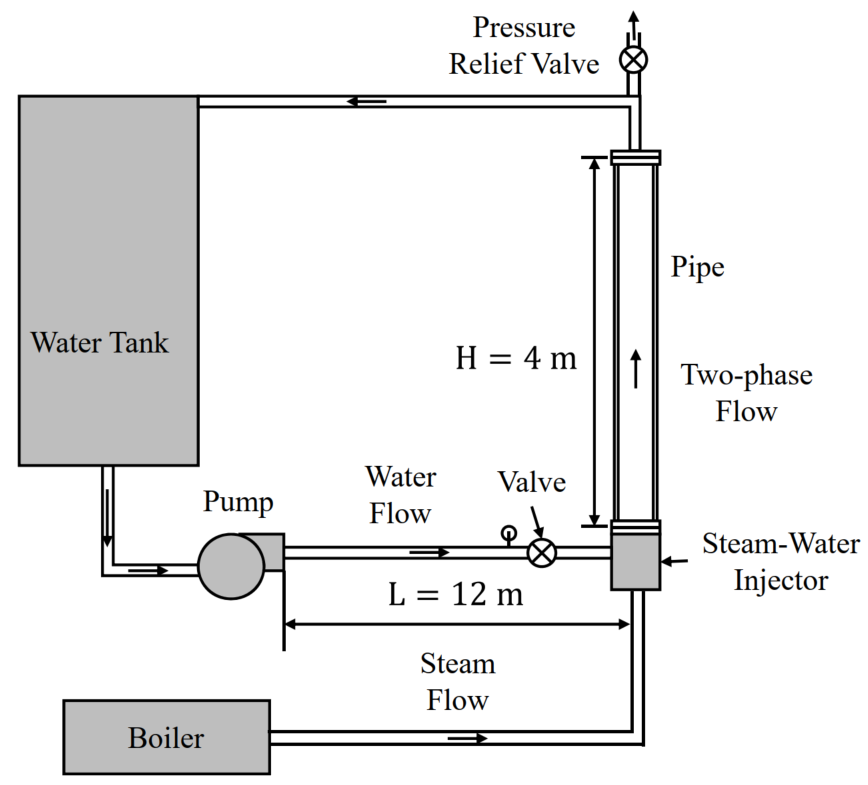
The figure shows the flow loop for the two-phase flow experiment in pipes. Water is driven by a pump and air is driven by an air compressor. They are mixed in the air-water injector, and then injected into the vertical pipe test section.
Assume that two phases flow in the vertical pipe with a diameter
Assume that the void fraction change along the flow direction is negligible.
Fluid properties are given by:
The answer should be given using
Answer: The two-phase hydrostatic pressure gradient is given by:
If the pipe height is
Q5-5
Following Question 4, calculate the two-phase frictional pressure gradient using the Lockhart-Martinelli method. What is the two-phase frictional pressure loss in the vertical pipe if the pipe length is
- Laminar flow:
- Turbulent flow:
Two-phase multiplier is given by:
where
| Liquid | Gas | C |
|---|---|---|
| Turbulent | Turbulent | 20 |
| Laminar | Turbulent | 12 |
| Turbulent | Laminar | 10 |
| Laminar | Laminar | 5 |
The answer should be given using
Answer: The relevant formulas:
The reynolds number about the liquid and gas are calculated by:
Both gas and liquid flows are turbulent. Thus, liquid and gas friction factors are calculated by:
Then, liuquid and gas pressure gradients are calculated by:
Then, the Lockhart-Martinelli coefficient is given by:
Eventually, we have
Q5-6
Assume that pipes for transporting water has the diameter (
Answer:
According to Question 7, the liquid velocity in the pipe test section is:
Then, the liquid volumetric flow rate is:
Then, the liquid velocity in the water pipe is:
Then, the liquid single-phase Reynolds number is:
The liquid single-phase flow is turbulent. Thus, the single-phase friction factor is:
Then, the liquid single-phase frictional pressure gradient is:
Then, the liquid single-phase frictional pressure loss is:
Q5-7
Assume that the total pressure loss from pump to the top of the test section consists of a pressure loss due to the horizontal single-phase liquid flow and a pressure loss due to the upward two-phase flow in the vertical test section. Use the values calculated in Questions 4 to 6 to obtain a total pressure loss. The answer should be given using
Answer:
The total pressure loss is equal to: